GENERAL INFORMATION FOR JUNCKERS BATTEN SYSTEM
Solid Hardwood Flooring | Batten System Information
C 1.2
C 1.2
Fig. 1
JUNCKERS BATTEN SYSTEMS
C 1.0 General information
C 1.2 Batten System Information Specifier's Information Laying Instructions
INTRODUCTION
This information describes the general conditions for use and specification of Junckers traditional Batten System as well as Junckers Level 78+ Batten System. Both systems are suitable for residential and commercial use, and can be laid in combination with under floor heating.
The Batten Systems are load-bearing floor systems in which Junckers solid 2-strip boards or planks are nailed to battens which are levelled up on a firm subfloor.
Junckers solid hardwood boards can also be nailed to load-bearing wooden subfloors such as softwood floorboards or plywood.
NAILING TO BATTENS AND JOISTS
Only 22 mm and 20.5 mm boards can be nailed to battens and joists and must adhere to the prescribed 10-board rule. Secret nailing of boards is recommended, at an angle of 45° using Junckers J-Nails, 2.5 x 65 mm type-T machine nails or 2.8 x 65 mm wire nails. To ensure that the nail has the necessary shearing strength, it is important to adhere to Junckers’ above mentioned requirements for machine nails.
Alternatively, 4.2 x 45 mm screws (UK: 45 x no. 4 screws) can be used after predrilling using a 3.5-4.0 mm drill.
Nailing in full square timber such as 100 x 100 mm must be in the outermost third of the joist, so that wire nails do not make contact with any shrinkage cracks in the middle of the joist.
NAILING TO LOAD BEARING WOODEN SUBFLOORS
All thicknesses of boards can be nailed to load bearing subfloors of plywood or floorboards.
The subfloor itself must be of adequate stiffness and be flat with a maximum deviation of 2 mm under a 1.5 m straight edge (UK: 3 mm under 2 m).
The best result is achieved by nailing through the subfloor into the battens or joists.
As an intermediate layer floor cardboard, 500 g/m² are used.
LEVELNESS
Battens and joists must be straight with no distortion.
After installation the top surface of the battensor joists may deviate maximum 2 mm from flat level under a 1.5 m straight edge (UK: 3 mm under a 2 m straight edge), both across and along the individual battens or joists.
With joists this can be achieved by mounting strip ledges or firing pieces
SPACING OF BATTENS AND JOISTS
Spacing of battens or joists is determined according to the use of and expected load on the floor.
Table 2 presents batten and joist spacing normally used for 22 mm 2-strip boards:
|
Loading categories |
Middle battens | First and last battens | Remarks |
| A+B Residential + offices and commercial | 800 mm | 550 mm | Only for joists min. 100x100 mm |
| 600 mm | 500 mm | Standard batten centres. | |
| 500 mm | 400 mm | If deflection critirion for wheel load should be complied with | |
| 300 mm | 250 mm | Batten centres for 0.9 m length boards. | |
| C1 + C2 | 500 mm | 400 mm | If deflection critirion for wheel load should be complied with |
| C3 + D1 | 411 mm | 350 mm | For board length 3700 mm. Support all header joints. |
Table 3 presents batten and joist spacing normally used for 20.5 mm Planks:
| Loading categories | Middle battens | First and last battens | Remarks |
| A+B Residential + offices and light commercial | 500 mm | 400 mm | Standard batten centres |
| 400 mm | 350 mm | If deflection critirion for wheel load should | |
| C1+C2+C3+D1 | 400 mm | 350 mm | Max. batten centres. Adjust batten centres to support all header joints. |
SPACING OF PACKINGS
Recommended maximum packing centres for selected batten dimensions in different load classes, see Table 4.
At the end of all battens, at joints between battens and on battens with notches the span width L is used, see Fig. 3. Other packing pieces are spaced as Lmax but to a minimum number of three pieces, see Fig. 3.
Information on load classes, see C 1.0 - Table 1.
| Batten sizes | Residential (a), commercial and light industry (b) | Public buildings (C1, C2, C3) and shopping areas (D1) | ||
| width x height | Lmax mm |
Lend mm |
Lmax mm |
Lend |
| 40 x 39 (engineered) |
550 | 500 | 440 | 400 |
|
40 x 63 |
890 | 800 | 710 | 640 |
| 56 x 38 | 550 | 450 | 400 | 300 |
| 45 x 45 | 600 | 500 | 500 | 350 |
| 48 x 50 | 700 | 600 | 550 | 450 |
| 45 x 95 | 1350 | 1100 | 1050 | 850 |
| 50 x 100 | 1450 | 1200 | 1150 | 950 |
Fig. 3
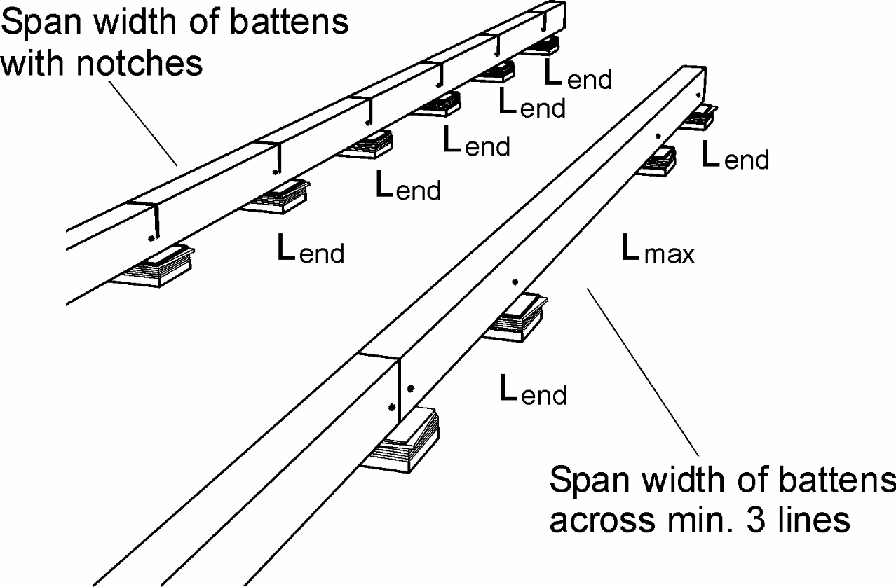
Fig. 4
DIMENSIONING ASSUMPTIONS
Dimensioning assumptions for spacing of packing.
Moisture class: Internal
Wood quality: Well-selected
Static system: Battens continuous across at least 3 bays (Lmax).
At the end line the packing distance is reduced equivalent to simple support (Lend).
Deflection, U (mm) max:
U < L/500 for useful load q
U < L/200 for useful load Q
U < 2.5 mm(Packing distance, L (mm))
STIFFNESS AND LOADBEARING STRENGTH
The stiffness and loadbearing strength of batten and joist structures depend on the type of load and load area, the spacing of battens and joists and the bond pattern of boards, including any support of board ends, see table 2.
Table 1 presents the stiffness and loadbearing strength in relation to load classes. For further definition of load classes and types: see C 1.0 - Stiffness and loadbearing strength.
| Loading types | ||
| Loading category | Area- and Point load | Wheel load |
| A+B: Residential + office |
Approved | - |
| C1+C2+C3+D1: Public bld. + shopping areas |
Approved | Approved |
Fig. 2
Criterion for deflection
Criterion for deflection in connection with spacing of battens and joists. Deflection U (mm) max.: U <L/700 for useful load q (kN/m ) U < L/200 for useful load Q (kN) U < 2.5 mm (Spacing of battens and joists, L (mm))
10-BOARD RULE
In order to minimize stress, distortion or gaps in the floor due to fluctuations in the climatic conditions within the building, boards must be laid according to a 10-board rule.
This indicates the measurement across 10 boards when laid and should be checked continuously during installation and afterwards, see Fig. 5.
The 10-board measurement is chosen on the basis of the expected maximum relative humidity in the building when in use throughout the year. The size of the floor, as well as it’s placing, i.e. ground floor or floor division, may also have an influence and the choice of the 10-board measure.
Fig. 6 illustrates the 10-board rule in relation to the relative air humidity for 129 mm boards. E.g. an expected relative humidity of max. 65% RH will normally require a 10- board measurement as indicated in table 5. For Junckers Shipsdecking floors a 10-board measurement is always used so that on assembly the shipsdecking strip is always slightly compressed, see table 5.
| 10-board measurement | ||
| Board width | Normal boards | Shipsdecking |
| 129 mm | 1293 mm | 1298 mm |
| 140 mm | 1403 mm | 1408 mm |
| 185 mm | 1853 mm | 1858 mm |
The relative humidity in office buildings, shops and similar can deviate from that in residential buildings, thus requiring a different 10-board rule.
In case of doubt please contact Junckers Technical Service.
Fig. 5
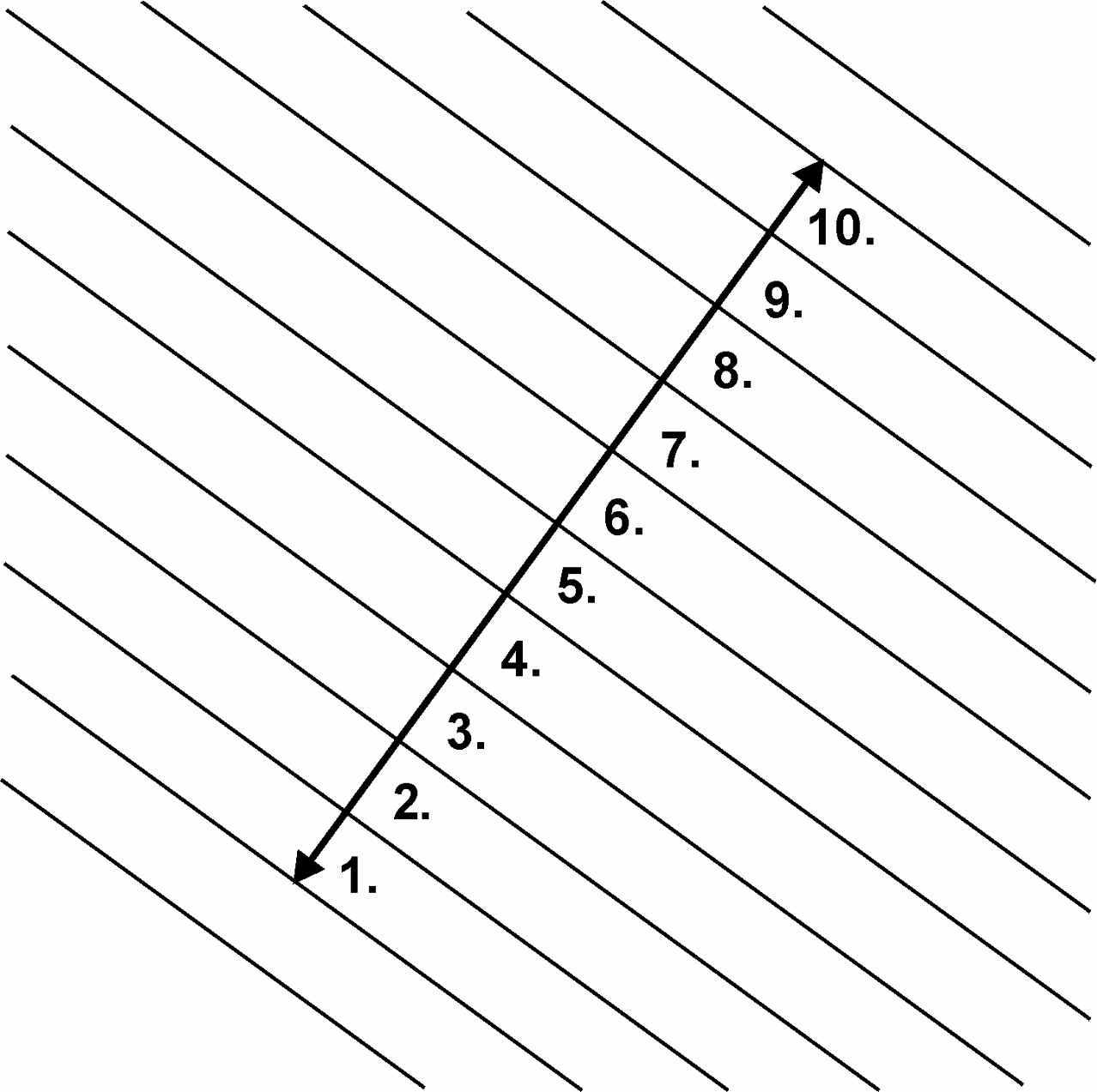
Fig. 6
THERMAL INSULATION
Batten and joist structures provide good opportunities to incorporate thermal insulation. Generally, thermal insulation should be incorporated directly over boiler rooms.
All central heating, cold and hot water pipes under floors must be carefully insulated using at least 20 mm mineral wool or similar. As a rule a minimum 10 mm air cavity should be present between the underside of boards and pipe insulation, see Fig. 7.
MOISTURE PROTECTION
At ground level and in floor structures subject to a risk of moisture, a protection against dampness from both residual and ground moisture is required.
A moisture barrier is established by laying a damp-proof membrane, 0.20 mm PE membrane or 1000 g polythene directly on the concrete before laying out the battens, see Fig. 7.
The residual moisture contained in the concrete or screed should not exceed 90% RH (UK: Concrete moisture max. 75% RH acc. to BS 8201, when checked by measurement). If the residual moisture is above 75% RH (UK: Concrete moisture max. 75 % RH allowed, see above), all overlaps must be taped using 50 mm wide tape.
Where the batten system is mounted on upper floor structures of reinforced concrete etc., a separate moisture barrier may not be required, provided that the floor is completely dry (max. 50% RH checked by measurement). Above wet rooms or archway structures or unheated rooms, a moisture membrane of a 0.20 mm PE membrane is laid directly on the concrete.
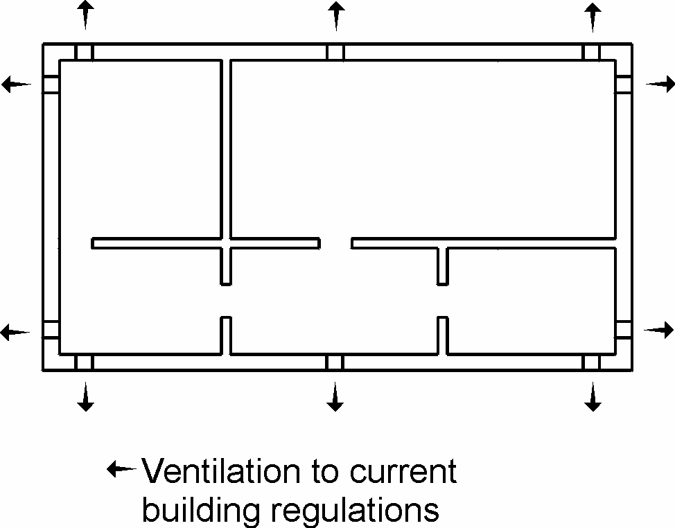
On joists across ventilation spaces a damp-proof membrane is laid, e.g. 0.20 mm PE membrane or 1000 g polythene. As a general rule the membrane is placed across the insulation, i.e. on the joists immediately below the boards, provided that the ventilation space is effectively ventilated to the outdoors and that the underside of the construction is open to diffusion, so as to eliminate the risk of fungal attacks in the joists, see Fig. 8.
In special cases, e.g. in holiday homes, heating and insulation conditions can be vital to the functioning of the damp-proof membrane, requiring it to be placed in a different way to that described above. In such situations it is advisable to request the assistance of Junckers Technical Service Department.
Fig. 7
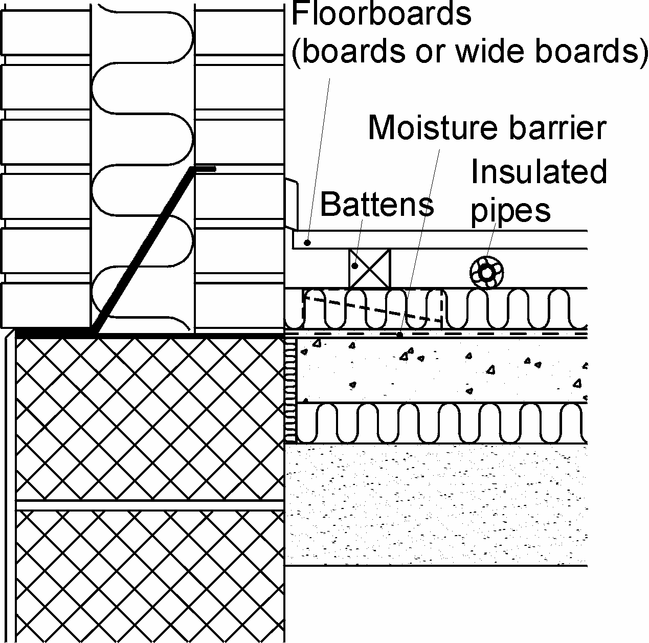
Fig. 8