LAYING INSTRUCTION FOR JUNCKERS GLUE DOWN SYSTEM
Solid Hardwood Flooring | Glue Down laying instruction
C 1.3.2
C 1.3.2
Fig. 1
C 1.0 General information
C 1.3 Glue Down System Information
C 1.3.1 Specifier's Information
C 1.3.2 Laying Instructions
BEFORE AND DURING LAYING THE FLOOR
The building must be weather tight. The heating system must be installed and tested and during the heating season should be in operation. Cast concrete elements, screeding and other wet trades, which contribute moisture to the building, e.g. tiling, plastering and priming of paintwork, must also be completed.
The relative humidity in the building must be between 35 - 65% RH and the temperature approx. 20° C. The subfloor must have a uniform, firm and clean surface and be sufficiently dry, see section 2 below, which is documented by control measurement. In wooden based subfloors the moisture content should not exceed 12%.
Solid boards should always be laid immediately on their arrival at the building. The packing on the bundles must not be removed until just prior to laying the floor, i.e. no acclimatising of the boards on site must take place.
NB: Read these laying instructions carefully before laying begins.
In case of doubt please contact your Junckers distributor before installing the floor.
Fig. 2
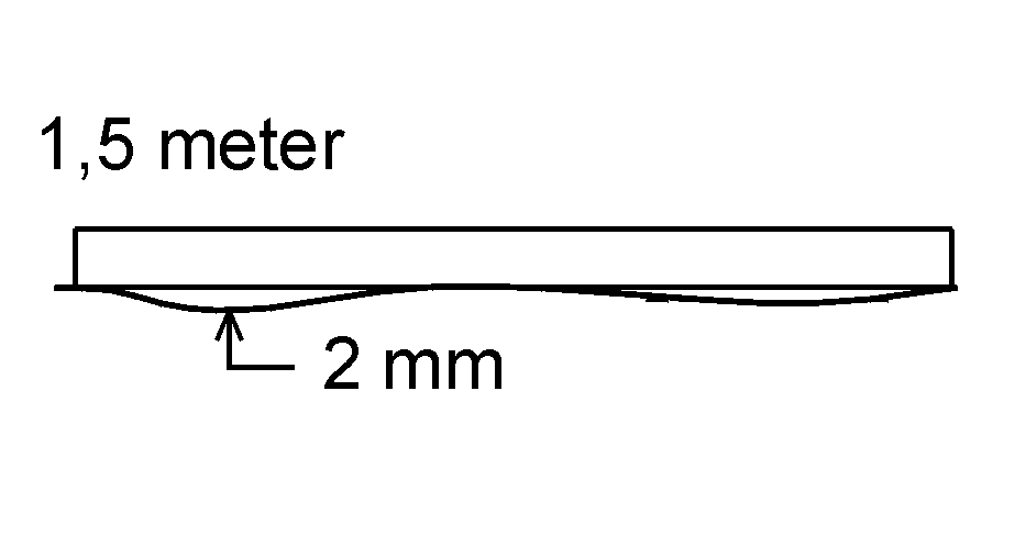
1. SUB-FLOOR CONDITION
The sub-floor must be levelled to a tolerance of no more than 2 mm gap showing under a 1.5 m straight edge (UK: No more than a 3 mm gap showing under a 2 m straight edge).
The surface must be smooth with no roughness. Local irregularities, e.g. above day joints, must be levelled.
To ensure a sufficiently firm and clean surface for optimum adhesion the subfloor should be filled or sanded prior to laying.
Fig. 3
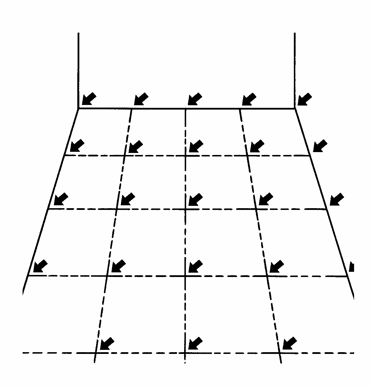
2. SUB-FLOOR CONDITION
Before laying begins it must be ensured that the residual moisture in the concrete does not exceed 75% RH.
NB: In the case of underfloor heating, Junckers Liquid Moisture Barrier must be applied, and the underfloor heating system must be switched off while the floor is being laid.
The floor surface is divided into a grid of modules of approx. 5-10 m2 each. The measurements are then taken at each intersection in the grid, using e.g. a capacitive moisture gauge to find the areas with the highest RH. The residual moisture in the areas with the highest RH is then measured using a destructive measuring method, see C 1.3.
NB: Some knowledge and experience of moisture measurement is required for the interpretation and evaluation of the moisture content of a structure. Such measurements should therefore be carried out by an expert.
IMPORTANT: In case the maximum residual moisture content is exceeded, Junckers Liquid Moisture Barrier are used, see H 6.5.
Fig. 4
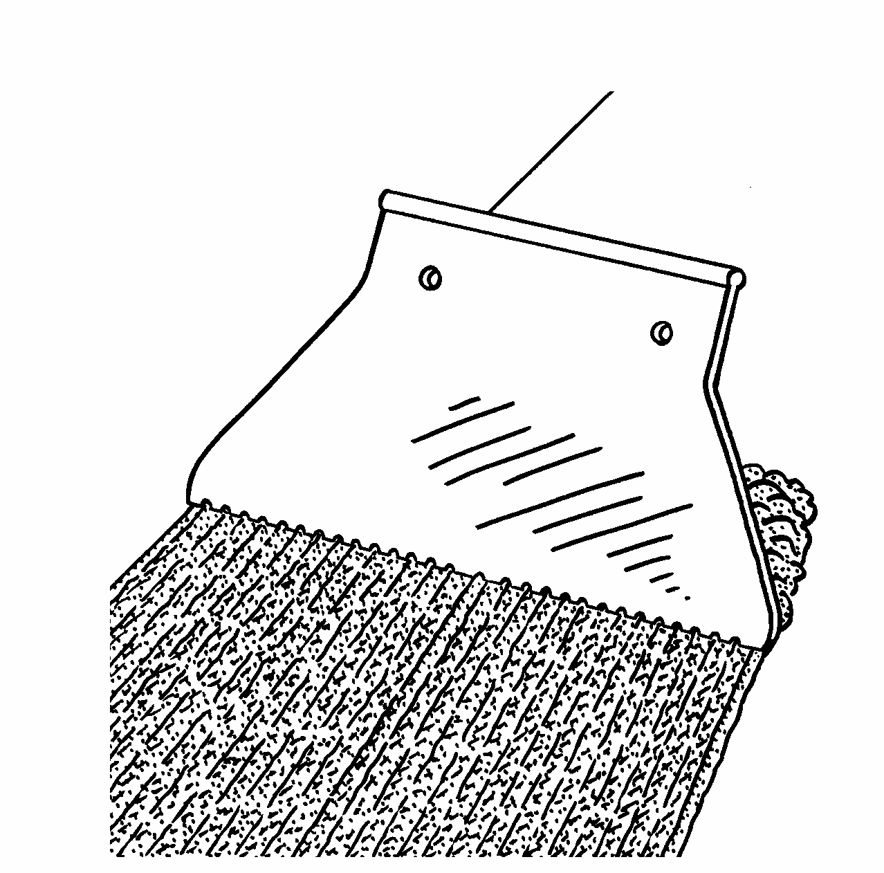
3. LAYING WITH GLUE DOWN SYSTEM
Use Junckers Parquet Glue for the glue down system. The glue is applied using the Junckers spatula, leaving a thin glue coat on the floor between the glue tracks. Hold the spatula at an angle of under 45° and with the side marked 2 turned downwards.
Use approx. 0.5-0.6 litre per m², depending on the absorption capacity, structure and flatness of the subfloor.
Subfloors with a high absorption capacity should be primed with Junckers Liquid Moisture Barrier to ensure optimum adhesion.
The glue is usually applied to an area equivalent to 3-4 rows of boards at a time, and never exceeding an area in which the boards can be fitted within 20-30 minutes before the glue starts to cure.
Fig. 5
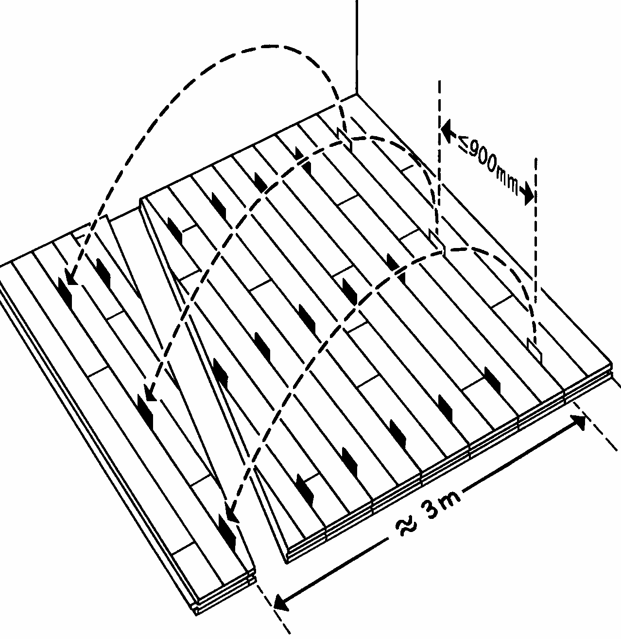
4. INSTALLATION AND 10-BM
Press the boards firmly into the wet glue and place the boards with spacers in between every row of boards at max. 900 mm in order to achieve the required 10-board measure, 10 BM.
For buildings where the maximum relative humidity of the air will be 65% RH, on gluing to a concrete ground floor use 0.4mm spacers (10 BM = 1294 / 1404 / 1854 mm). On gluing to a wooden based subfloor or concrete upper floor, use 0.2 mm spacers (10 BM = 1292 / 1402 / 1852 mm). For buildings with a relative humidity of the air exceeding 65% RH, see C 1.3.1.
While laying the floor be sure to use spacers equivalent to 3 m back in the laying direction, after which the glue will have dried/hardened sufficiently, and the spacers first laid can be taken up and re-used.
For shipsdecking always use a 10-BM equivalent to slight tightening of the Shipsdecking strip while laying (10 BM = 1298 / 1408 / 1858 mm). Spacers are not used in this case.
Fig. 6
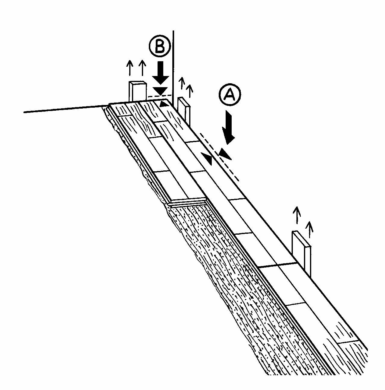
5. INSTALLATION AND EXPANSION GAPS
Press the boards down on the wet glue and join them loosely, so that 10 boards cover as specified in section 4.
Expansion gaps to walls and fixed installations must be 1.5 mm per running metre of floor width on each side (A), and 1 mm per running metre of floor length at each end (B), all with a minimum size of 12 mm (UK: 15 mm).
Use temporary spacers or wedges between the wall and the boards to form the expansion gap.
Fig. 7
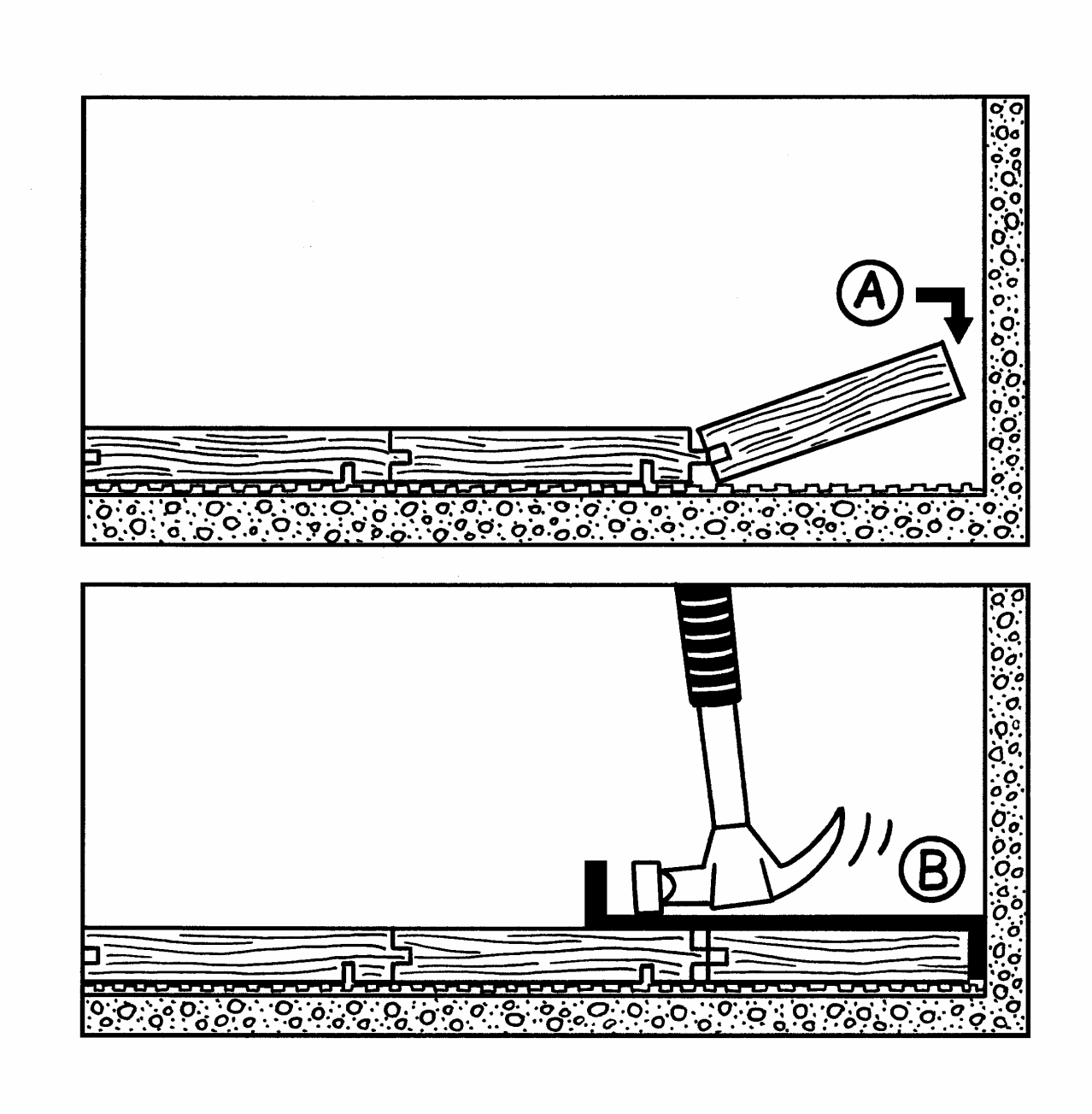
6. BOARD PATTERN
Lay the boards in a random joint pattern. Distribute the header joints as far apart as possible. The distance between board header joints in two successive rows should be at least 250 mm.
Stave joints in one row of boards should not be in line with stave joints in a neighbouring row, but must be spread as far as possible (min. 50 mm).
Cut the last row of boards to form the correct size of expansion gap at the wall.
Use a joint puller (B) to slot the last board into place. Remove temporary spacers or wedges before installing skirtings
Fig. 8
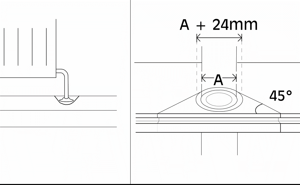
7. VARIOUS
Around pipes, drill a hole in the board to accommodate the pipe. The space around the pipe must be the same as the expansion gap at the wall.
A tapered wedge is cut out, so that it can be glued in place. This gap is covered using a radiator pipe cover.
At door frames and architrave’s, cut the base of the frame and architrave to allow the floor to fit underneath.
At the threshold the expansion gap can be covered by a threshold strip or, if levels reduce, fit a ramp.