SOLID HARDWOOD FLOORING
CLIP SYSTEM INFORMATION
Underfloor heating
Commercial / Residential
E 4.1
E 4.1
Fig. 1
UNDERFLOOR HEATING
E 4.0 General Information
E 4.1 Clip System Information
INTRODUCTION
These instructions apply to all Junckers Solid hardwood boards laid with clips on concrete or screeded subfloors with built-in underfloor heating.
Please note that full documentation of a floor system laid on a subfloor with underfloor heating comprises the data in E 4.0 and E 4.1, see Fig. 1.
Reference is also made to Junckers Clip System, see C 1.1.
COMPONENTS
1 - Boards
• Junckers 14 and 22 mm 2-strip boards, incl. ships decking
• Junckers 15 and 20.5 mm Planks, incl. shipsdecking.
2 - Clips
3 - Intermediate layer
• Junckers PolyFoam
4 - Extra moisture barrier
• 0.20 mm PE membrane
5 - Concrete or screeded subfloor
6 - Heating pipes or cables
7 - Reinforcement
8 - Insulation
9 - Concrete deck
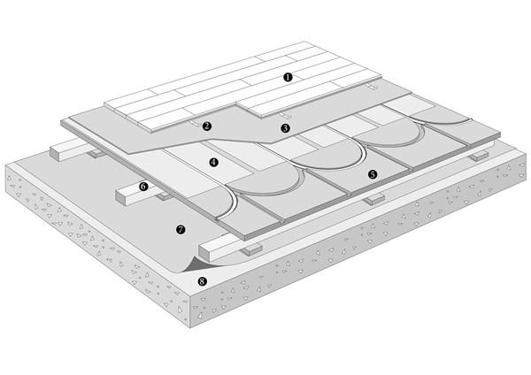
Fig. 2
CLIP SYSTEM ON SUBFLOOR WITH CAST-IN HEATING PIPES
The clip system can be laid on concrete or screeded subfloors with cast-in heating pipes or cables. It is extremely important that the floor heating system is designed to achieve a stable temperature across the surface of the concrete or screed. The following applies to heating pipes in concrete or screeded floors:
To ensure an even temperature distribution, on casting there must be min. 30 mm of concrete or screed above the heating pipes. The pipes should not be spaced more than 300 mm apart, and the cables not more than 150 mm apart.
Before the Junckers floor is laid the heating system must have been in operation for at least 2 weeks at 2/3 power and 2 days at full power. During this period the room must be ventilated briefly every day. The moisture content of the concrete or screed must not exceed 65% RH (UK 75% RH).
For clip systems laid on concrete or screed, with cast-in heating pipes or cables, an intermediate layer of PolyFoam is used and beneath it a 0.20 mm PE membrane with a 200 mm overlap, taped at the joints and turned up at the walls.
Fig. 3
COMPONENTS
1 - Boards
• Junckers 14 and 22 mm 2-strip boards, incl. ships decking
• Junckers 15 and 20.5 mm Planks, incl. shipsdecking.
2 - Clips
3 - Intermediate layer
• Junckers PolyFoam
4 - Extra moisture barrier
• 0.20 mm PE membrane
5 - Cementitious layer
6 - Heating mat
7 - Concrete or screeded subfloor
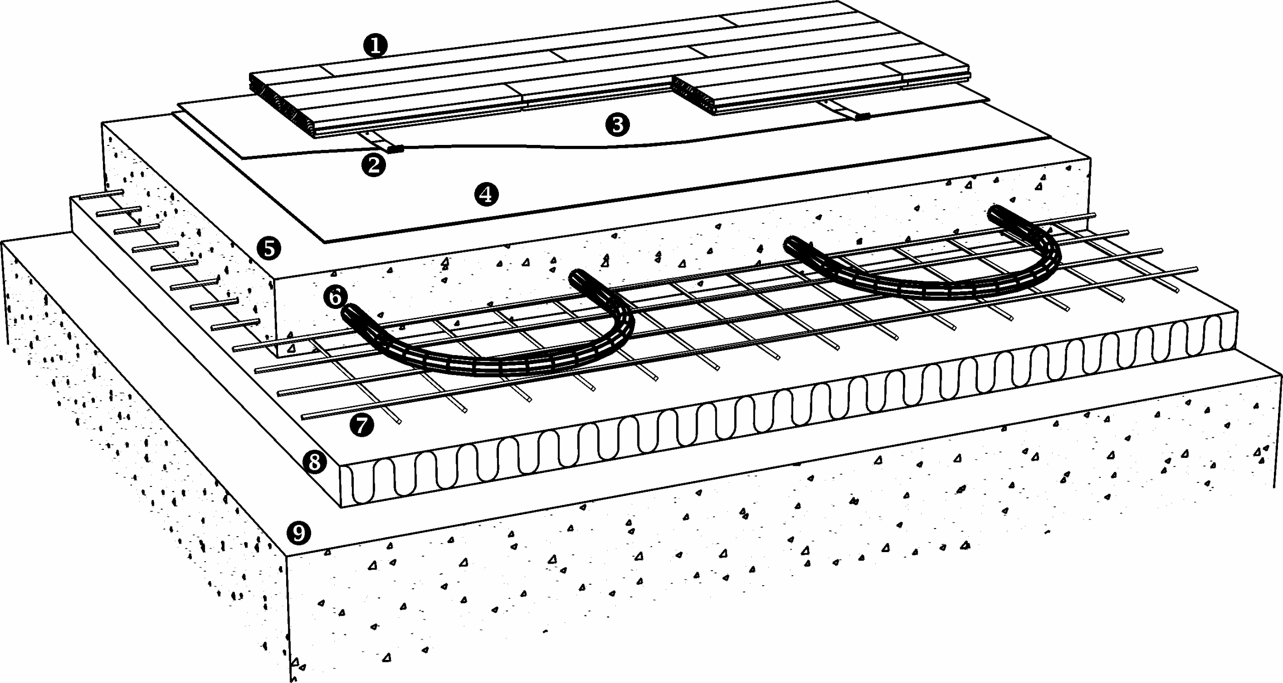
Fig. 4
CLIP SYSTEM ON CONCRETE WITH ELECTRICAL HEATING MAT
The clip system can be laid on concrete subfloors with a heating mat installed on the surface.
To protect the heating elements and to ensure an even heat distribution, cover the heating mat with a cementitious layer min. 6 mm thick. Prime the subfloor with floor primer before laying the heating mat.
In renovation work where the heating system is installed on an existing dry subfloor the clip system can be laid as soon as the cementitious layer is dry to 65% RH (UK 75% RH) and ready for covering. Follow the manufacturers instructions.
In cases where the heating mats are installed on to a new concrete subfloor, the floor can be laid when the temperature and humidity of the building correspond to the expected future climatic conditions of the building when in use, see C 1.0.
The residual moisture of the concrete must not exceed 65% RH (UK 75% RH). This can e.g. be achieved by turning on the floor heating system as required according to the conditions. During this period the room must be ventilated briefly every day.
An intermediate layer of PolyFoam is used for clip systems laid on subfloors with heating mats. Under this is laid a 0.20 PE membrane with a 200 mm overlap taped at the joints and turned up at the walls behind skirting boards.
Fig. 5
COMPONENTS
1 - Boards
• Junckers 14 and 22 mm 2-strip boards, incl. ships decking
• Junckers 15 and 20.5 mm Planks, incl. shipsdecking.
2 - Clips
3 - Intermediate layer
• Floor cardboard, 500 g/m²
• Load-distribution board:
22 and 20.5 mm floor boards: Residential: The clip system is laid directly on the heat-distribution plates. Commercial: The clip system is laid on a load-distribution board of min. 10 mm chipboard or plywood.
15 mm and 14 mm floor boards: Residential and commercial: The clip system is laid on a load-distribution board of min. 10 mm chipboard or plywood.
The load-distribution board is laid on the heat-distribution plates and under the intermediate layer. Make sure the distribution boards are staggered and taped together.
4 - Heat-distribution plates
5 - Heating pipes
6 - Polystyrene boards
• Density, min. 30 kg/m³
7 - Moisture barrier
• 0.20 mm PE membrane
8 - Concrete subfloor
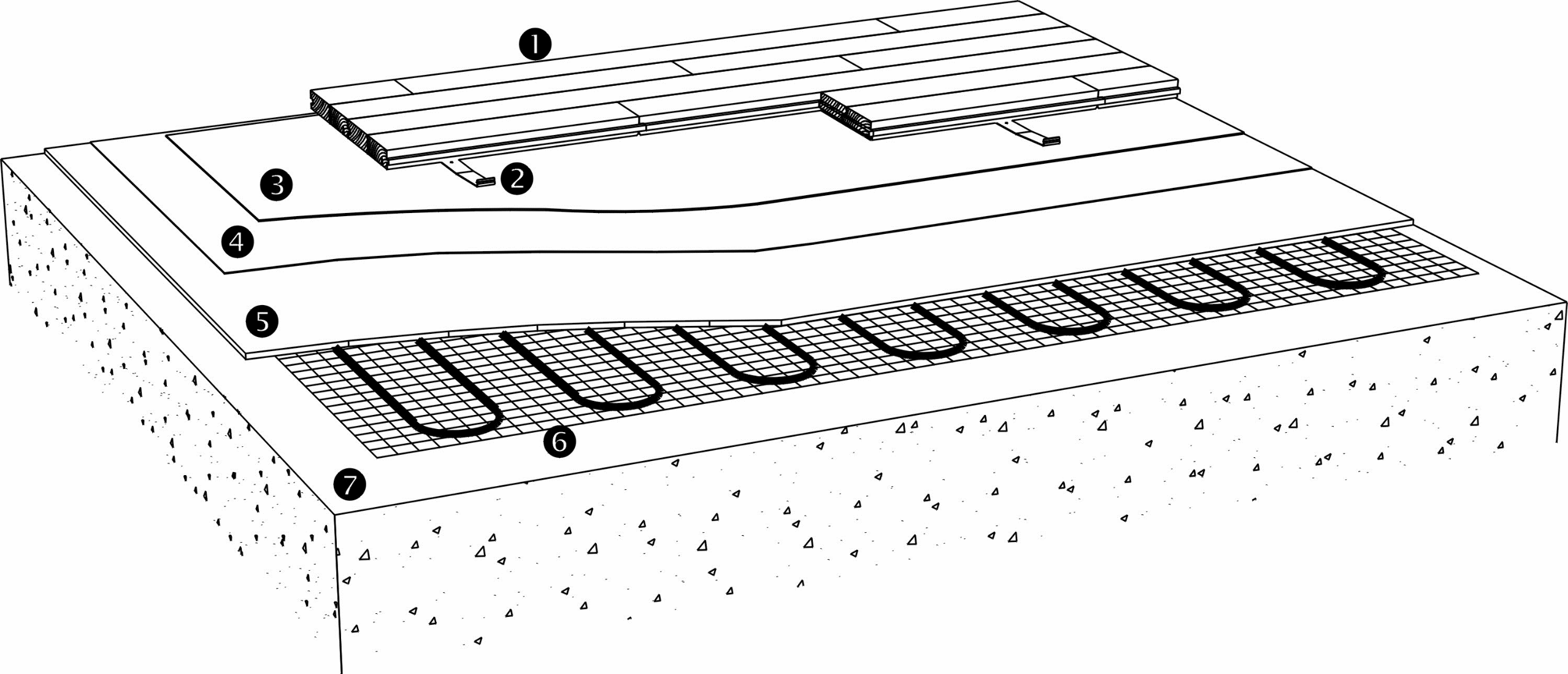
Fig. 6
CLIP SYSTEM ON POLYSTYRENE BOARDS WITH HEATING PIPES
The clip system can be laid on an underlay of polystyrene with the heating pipes set in heat-distribution plates. The intermediate layer is floor cardboard, 500 g/m². This system is not suitable for sports applications.
To ensure that the floor surface is sufficiently elastic, and depending on the board thickness, the load capability and the density of the polystyrene, it may be necessary to incorporate a load-distribution board, such as chipboard, under the clip system, see Fig. 6.
For further information please refer to the Specifier's Information, see C 1.1.1.
Fig. 7
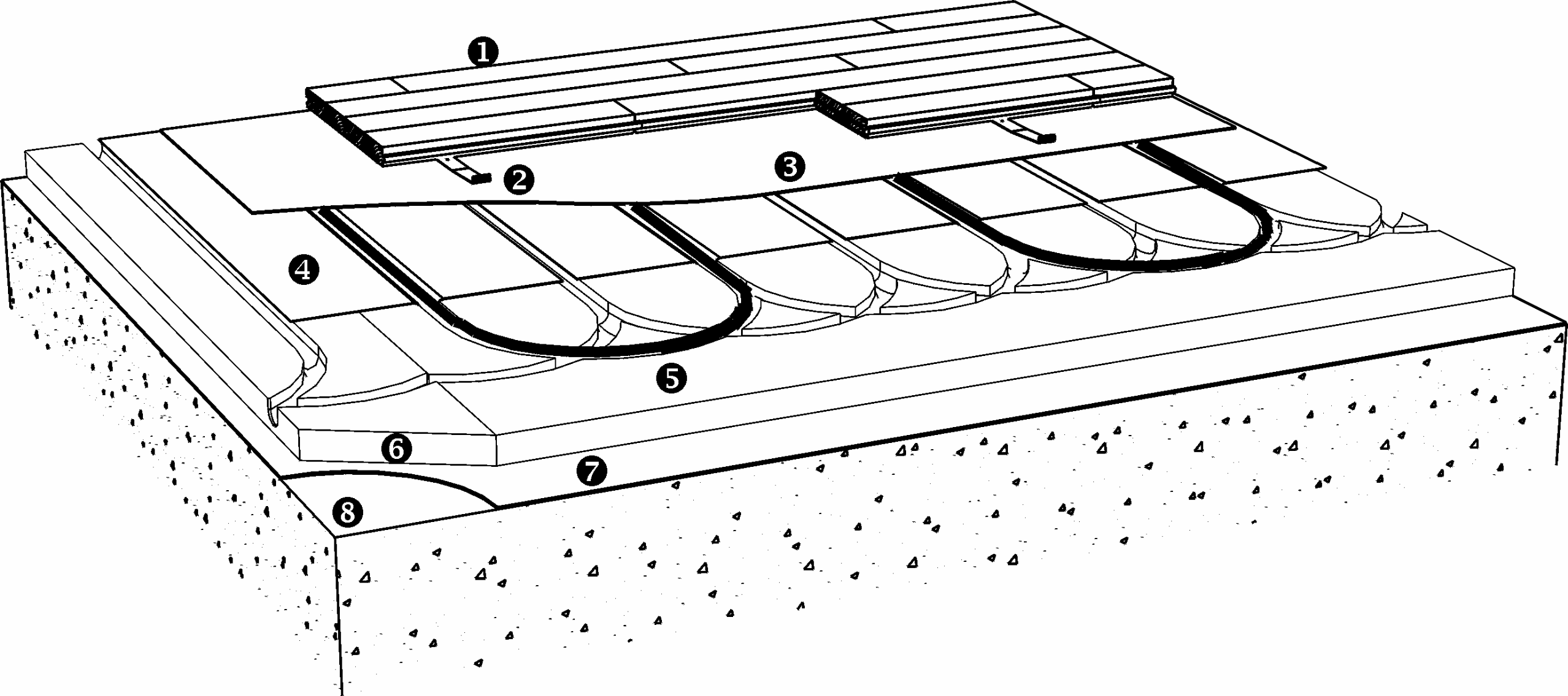
COMPONENTS
1 - Boards
• Junckers 14 and 22 mm 2-strip boards, incl. shipdecking
• Junckers 15 and 20,5 mm planks, incl. shipsdecking
2 - Clips
3 - Intermediate layer
• Junckers Foam
4 - Heat distribution plate
5 - Chipboard with heating pipes
6 - Battens
7 - Moisture barrier
• 0,20 mm PE Membrane
8 - Concrete
Fig. 8
CLIP SYSTEM WITH HEATING PIPES SET IN HEATDISTRIBUTION PLATES
The Clip System can be laid on an underlay of chipboard with the heating pipes set in heat distributionplates. The intermediate layer is Junckers Foam.
For further information please refer to specifiers information C 1.1.1.
Fig. 9