CLIP SYSTEM INFORMATION
JUNCKERS SPORTS FLOOR SYSTEMS
D 1.1
D 1.1
Fig. 1
D 1.0 General information
D 1.1 Clip System Information
D 2.1 Specifier's Information
D 2.1.1 Laying Instructions
INTRODUCTION
This data sheet describes the general conditions for specification of Junckers clip system for sports floors, see Fig. 1.
The information also applies to Junckers portable floor systems
SUBFLOORS
Subfloors may be of concrete, lightweight concrete or screed in connection with renovation may be an existing sports floor with e.g. a synthetic or wooden floor surface.
The elasticity of the subfloor has a direct impact on the properties of the completed floor in terms of deflection, impact absorption and ball bounce. In renovation projects the elasticity and load bearing strength of the existing floor must be assessed in relation to the use of the floor.
If the overall floor space is made up of several types of subfloor, it must be of uniform elasticity and flatness, to ensure that the final floor is uniform.
The moisture content of a wooden subfloor must be in balance with the relative humidity of the room, i.e. moisture content of 6-12%.
FLATNESS OF SUBFLOOR
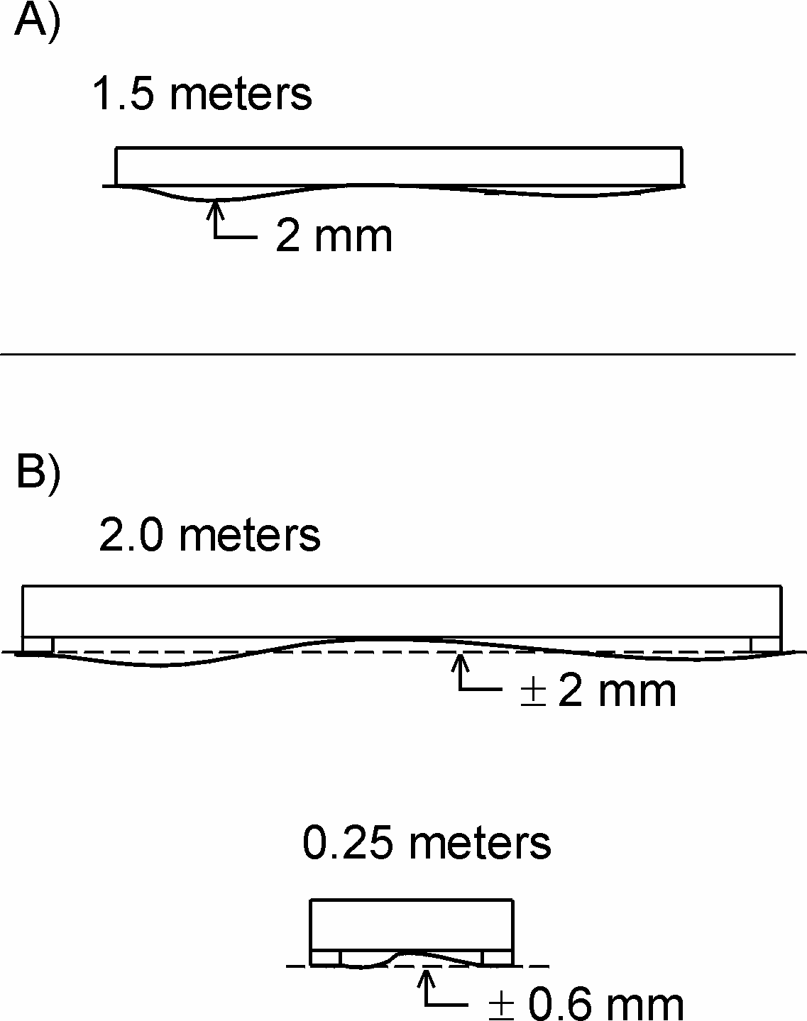
Before intermediate layers are laid the subfloor must be levelled so that any deviations in the flatness do not conflict with the requirements of one of the two methods stated below, see Fig. 2.
A) Traditional straight edge
The subfloor must be flat with a maximum deviation of 2 mm under a 1.5 m straight edge (UK: 3 mm under a 2 m straight edge). The surface must be smooth. Any minor irregularities mustbe corrected.
B) Straight edge with supports
The subfloor must be flat with a maximum deviation of ± 2 mm under a 2 m straight edge (2mm supports). The surface must be smooth. Any minor irregularities, e.g. across day joints, must be corrected so that the maximum localised deviation from flat level is ± 0.6 mm under a 0.25 m straight edge (0.6 mm supports).
Major irregularities on concrete floors can be corrected by using a self-levelling compound. Wooden subfloors may be levelled by sanding or installing hard fibreboards, possibly combined with filler, or by laying fibrous plasterboards.
Junckers Technical Information specifies the flat level requirements of subfloors as amaximum deviation of 2 mm under a 1.5 m straight edge (UK: 3 mm under a 2 m straight edge).
Fig. 2

INTERMEDIATE LAYER
The elasticity of the subfloor determines the choice of intermediate layer.
If the subfloor is wholly or partly inelastic Junckers 10 mm Sports Foam is used, while on elastic subfloors, e.g. existing sports floors with certain sport-related properties, Junckers 5 mm Sports Foam is used, see H 3.3.
MOISTURE PROTECTION
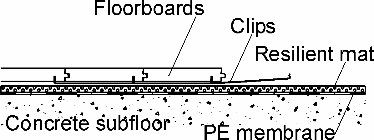
Concrete subfloors At ground and upper levels protection against moisture both from within the building and from the ground is required.
A moisture barrier is established by laying a damp-proof membrane, 0.20 mm PE membrane or 1000 g polythene, e.g. Junckers Moisture Barrier, directly on the concrete, see Fig. 3. The moisture barrier is laid with an overlap of 200 mm at all joints, continuing up walls, etc. All overlaps must be taped using 50 mm wide tape.
The residual moisture contained in the concrete or screed must not exceed 90% RH (UK: Concrete moisture max. 75% RH acc. to BS 8201, when checked by measurement).
Wooden subfloors
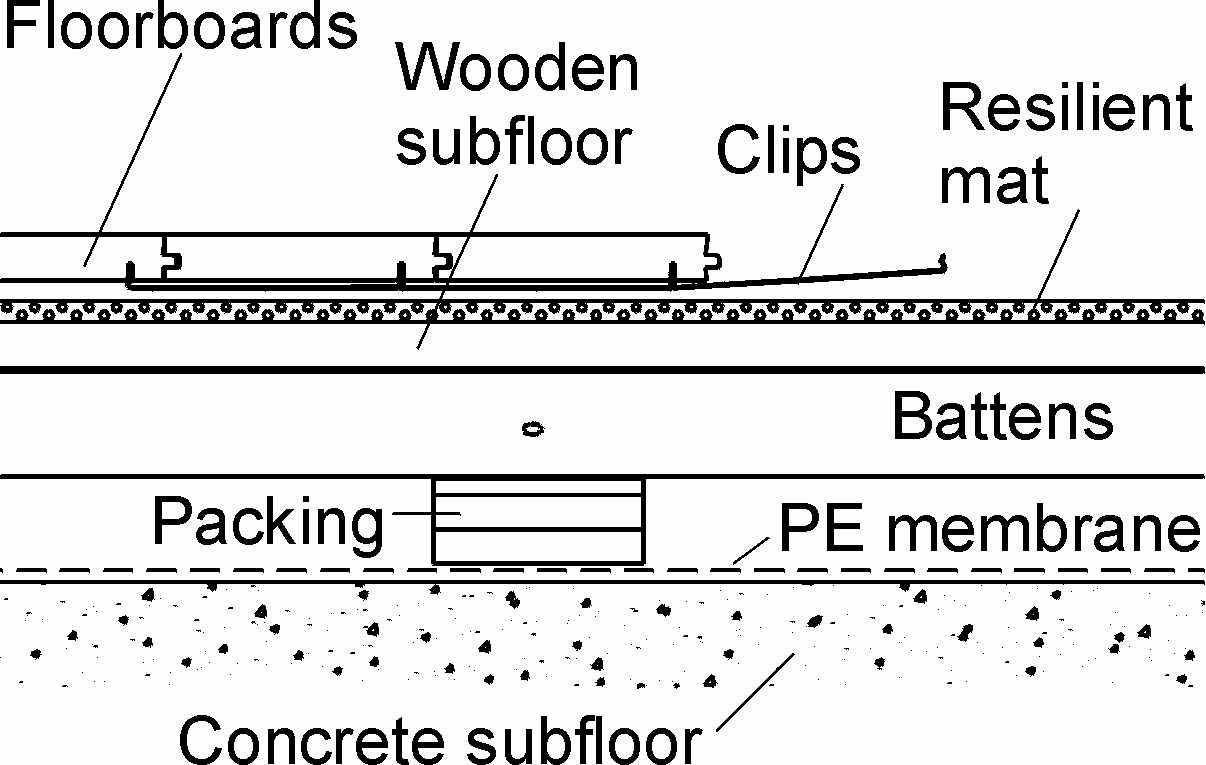
For renovation projects where floating floor systems are laid on existing wooden subfloors it must be ensured that the entire structure has been designed to the correct specifications regarding moisture. Usually, no additional moisture protection must be applied on top of the existing sports floor as this may course the risk of fungal attacks in the subconstruction, see Fig. 4.
Fig. 3

Fig. 4

EXPANSION GAPS AT WALLS AND FIXED INSTALLATIONS
For floors over 12 m wide the minimum expansion gap at walls and fixed installations must be 30 mm in order to allow for movement of the floor. In the case of especially wide spans it may be necessary for a gap of more than 30 mm to be formed. This is calculated at 2 mm per m width at the side. For floors under 7.5 m width the minimum expansion gap size can be reduced to 15 mm.
For the lengthwise of the floor, place expansion strip between the end of the boards and the wall.
Fig. 5

CLIPS
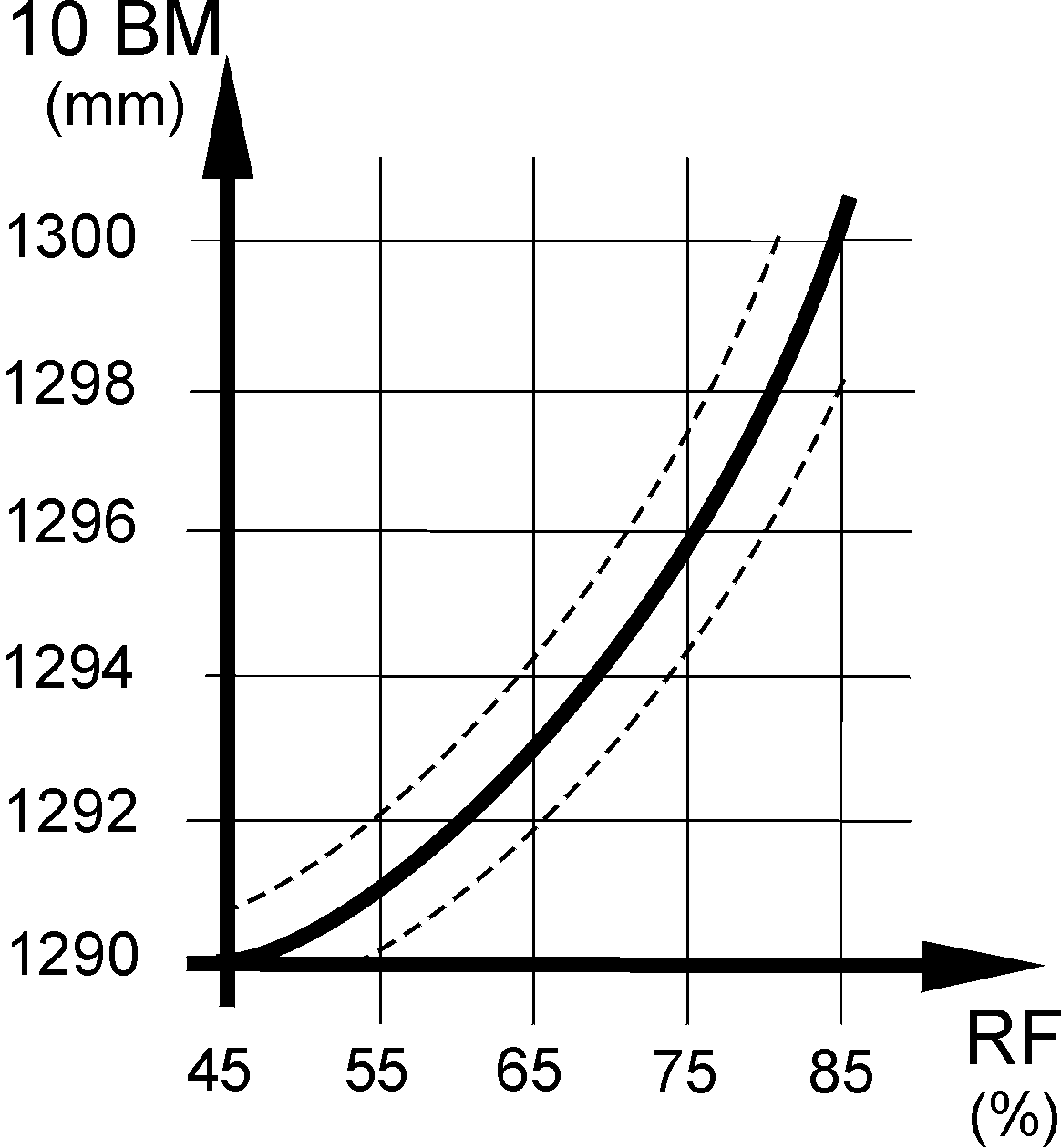
Clips are available in different sizes according to various air humidity ranges. The clip size is selected primarily on the basis of the expected maximum relative humidity, RH, in the building during the course of the year. However, in order to minimize the overall movements of larger floors it may be necessary to choose a larger clip than that corresponding to the expected maximum RH, see Table 1 and Fig. 5.
| Clip type (label colour) | Humidity range (%) | Clip size | Gaps between boards when installed |
| 0-hole (white) | 10-40** | 128.8 mm | depends on job-site conditions* |
| 1-hole (green) | 25-55** | 129.1 mm | 0.1 mm |
| 2-hole (yellow) | 40-65 | 129.4 mm | 0.4 mm |
| 2½-hole (Black) | 55-75 | 129.6 mm | 0.6 mm |
| 3-hole (red) | 65-85 | 129.8 mm | 0.8 mm |
| 4-hole (Orange) | 75-95 | 130.2 mm | 1.2 mm |
*This clip type is used in arctic- and desert areas. Acclimating of the wood prior to installation is necessary.
**In a very dry environment there will be some larger permanent gaps between the floorboards. Specifiers are advised to contact Junckers Technical department if such conditions are anticipated. With all clip sizes there will always be gaps when the relative humidity falls to, or below, the lower end of the recommended range.
