SOLID HARDWOOD FLOORING
GENERAL INFORMATION
Sound
Commercial / Residential / Sport
E 5.0
E 5.0
INTRODUCTION
This document provides general information on sound and practical guidelines on acoustics in floor constructions with Junckers solid hardwood flooring.
The Specifier's Information pages state recommended values for step-sound reduction and absorption coefficients for a wide range of Junckers flooring systems, see E 5.1.
Furthermore, reference is made to Junckers Floor Systems, see C 1.0.
Certain terms are used to describe acoustics, e.g. airborne sound and step sound. The most common terms can be found in the glossary at the back of this document
SOUND
E 5.0 General Information
E 5.1 Specifier's Information
Fig. 1
STATUTORY REQUIREMENTS
For building acoustics requirements, reference is made to national building regulations.
Fig. 2
GENERAL
In acoustics, both batten and clip systems are floating floors when laid as separate floor constructions on concrete decks or wooden joists and separated from the latter and from walls by means of intermediate elastic layers.
In batten floors for residential and commercial applications elastic soft wedges are used for packing. In batten systems for sports applications shock absorbing pads have similar properties.
Junckers PolyFoam or JunckersFoam underlays are used in clip systems for residential and commercial applications.
For sports applications, Junckers SportsFoam, 5 or 10 mm thick, are used.
AIRBORN-SOUND INSULATION
A dividing floors airborne-sound insulation, R´w, is first and foremost determined by the deck construction and by the flank transmission between the rooms, whereas the finished floor product generally has little importance.
Wooden floors on battens often have a positive impact, whereas, under certain circumstances, wooden floors on resilient underlays can slightly reduce the R´w value.
As Junckers floors are of little importance to the airborne-sound insulation in a separating floor, airborne‑sound insulation is not considered further in this General Information.
STEP-SOUND REDUCTION
On concrete separating floors or decks where step-sound reducing floor systems have been laid, e.g. a clip system, the step-sound level, L´n,w, can be calculated on the basis of the concrete decks step-sound level and the step-sound reduction of the Junckers floor system, e.g. the clip system. The decks step-sound level depends on the deck material, thickness and installation, and on the flank transmission in the building, whereas the Junckers floors step-sound reduction is uniform whether the Junckers floor is laid on a 185 mm concrete deck or on a 200 mm concrete cellular floor.
Step-sound reduction is deemed to mean the entire wooden floor construction of Junckers floor boards on battens or the clip system, including underlay.
On non concrete dividing floors, the step-sound level cannot be calculated on the basis of the step-sound reduction of the flooring alone, as this is often measured on a concrete dividing floor. This is first and foremost because on non concrete dividing floors there is a need for step-sound reduction at low frequencies, and at high frequencies on concrete dividing floors.
SOUND ABSORPTION
A rooms surfaces contribute to the rooms total sound absorption. A wooden floor mainly contributes to the absorption at low frequencies.
FOCUS ON CORRECT INSTALLATION
Acoustics in floor constructions to a great extent depend on correct instalation. In the following, a number of important aspects of batten- and clip systems are described.
Clip System
Subfloors for clip systems must be level and meet the required specifications. It is important to consider avoiding rebates or casting joints, as they may result in very unfavourable sound transmission. An uneven subfloor can thus reduce the step sound reduction figure in relation to the recommended step sound reduction for a given floor system.
Ensure that the subfloors corners and edges along walls are clean and appear sharp, and that they are free from concrete and plaster residue, so that the Junckers floor can expand freely without contact between abutment and subfloor or walls.
Junckers expansion strips, which are fitted closely between board ends and walls on the clip system, ensure that the board ends do not touch the walls. Without this the flank transmission would increase, see Fig. 3.
Batten Systems
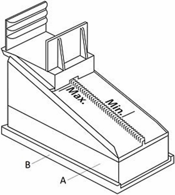
Junckers DuoWedges and Step Sound Reduction Pad are used for Junckers Level 78+ Batten System, see Fig. 4.
Fig. 3
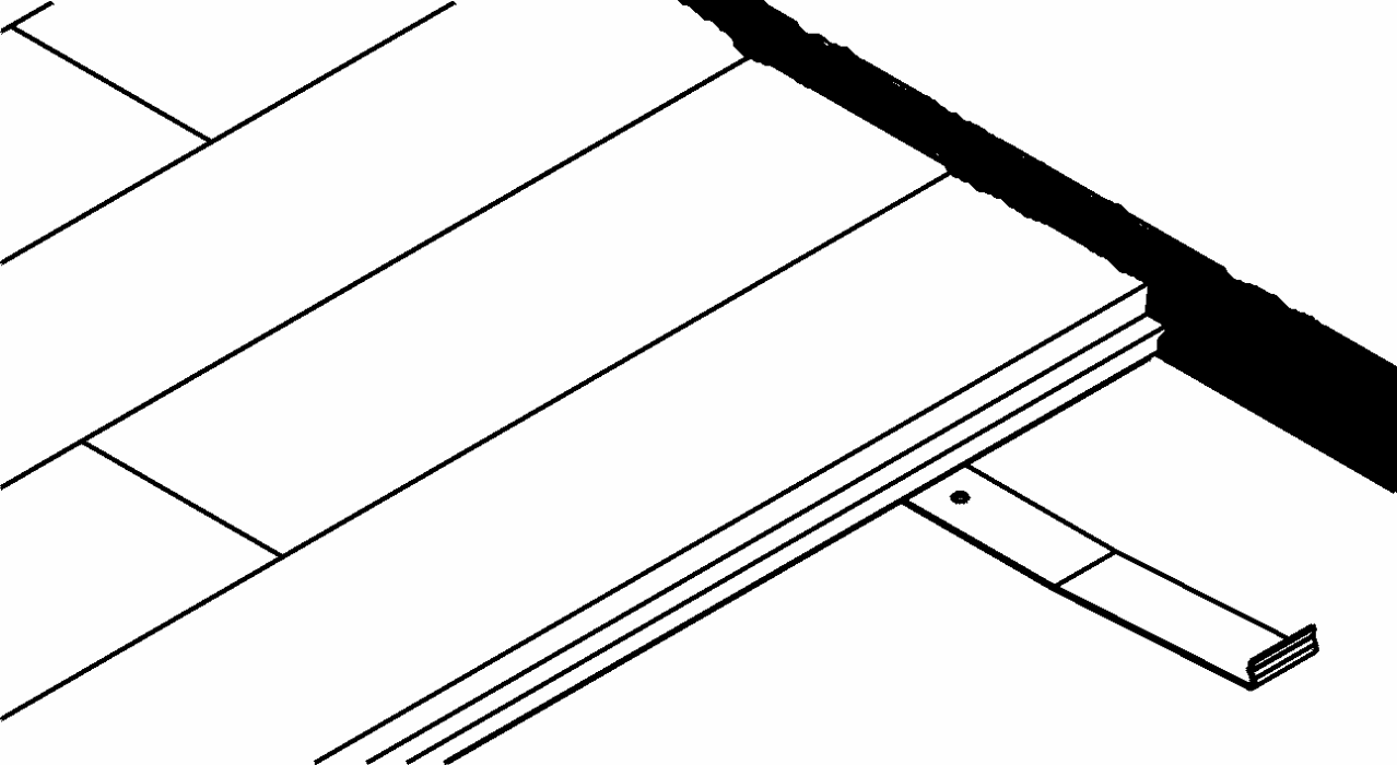
Fig. 4
Soft packings are used for packing/levelling of traditional batten systems, see Fig. 5.
The packings commonly consist of soft wooden fibre boards, and are placed at the lowest point of the elevation. Soft packings are made from 12-13 mm thick soft wooden fibre boards of 100 cm² e.g. 125 x 80 mm, and have a density of 225-300 kg/m³.
A plywood board, at least 12 mm thick, is glued on top. Packers are fixed to the battens with lost-head wire nails, which must never go into the soft material or touch the concrete. This would result in significant deterioration of the floors step-sound reduction properties. Alternatively, plastic wedges or foam backed cradles with similar properties may be used.
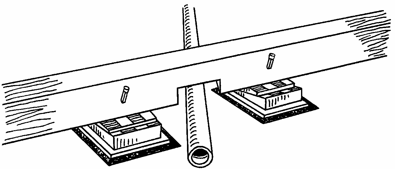
Packings/wedges must be close to cuts in the battens on both sides, see Fig. 6. There must be a minimum clearance of 10 mm between the lower surface of the board and batten and the pipe insulation to avoid sound bridges.
The recommended expansion gaps between battens and walls, and Junckers boards to walls and fixed installations must be followed to avoid contact between the floor construction and other structural parts, see Specifier's Information of each floor system.
Fig. 5
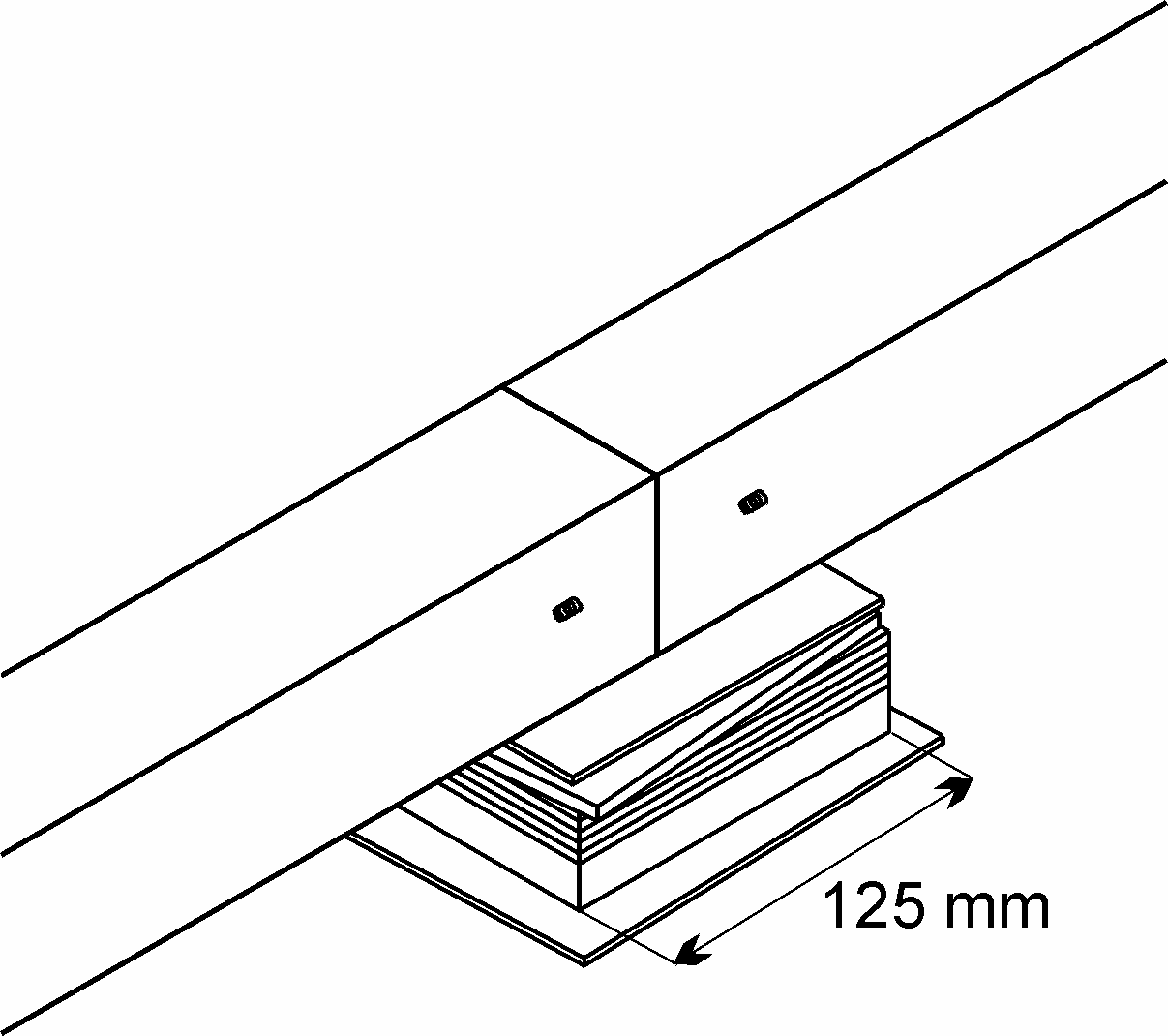
Fig. 6
GLOSSARY
Airborne sound
Sound that travels in the air, e.g. from a loudspeaker, is called airborne sound.
The airborne sound can pass through structures via openings or transmission through or radiation from structures, see Fig. 7.
Airborne-sound insulation, ∆Lw [dB]
A figure indicating the ability of a partition, e.g. a wall or a dividing floor, to prevent transmission of airborne sound, e.g. sound from a loudspeaker, see Fig. 7.
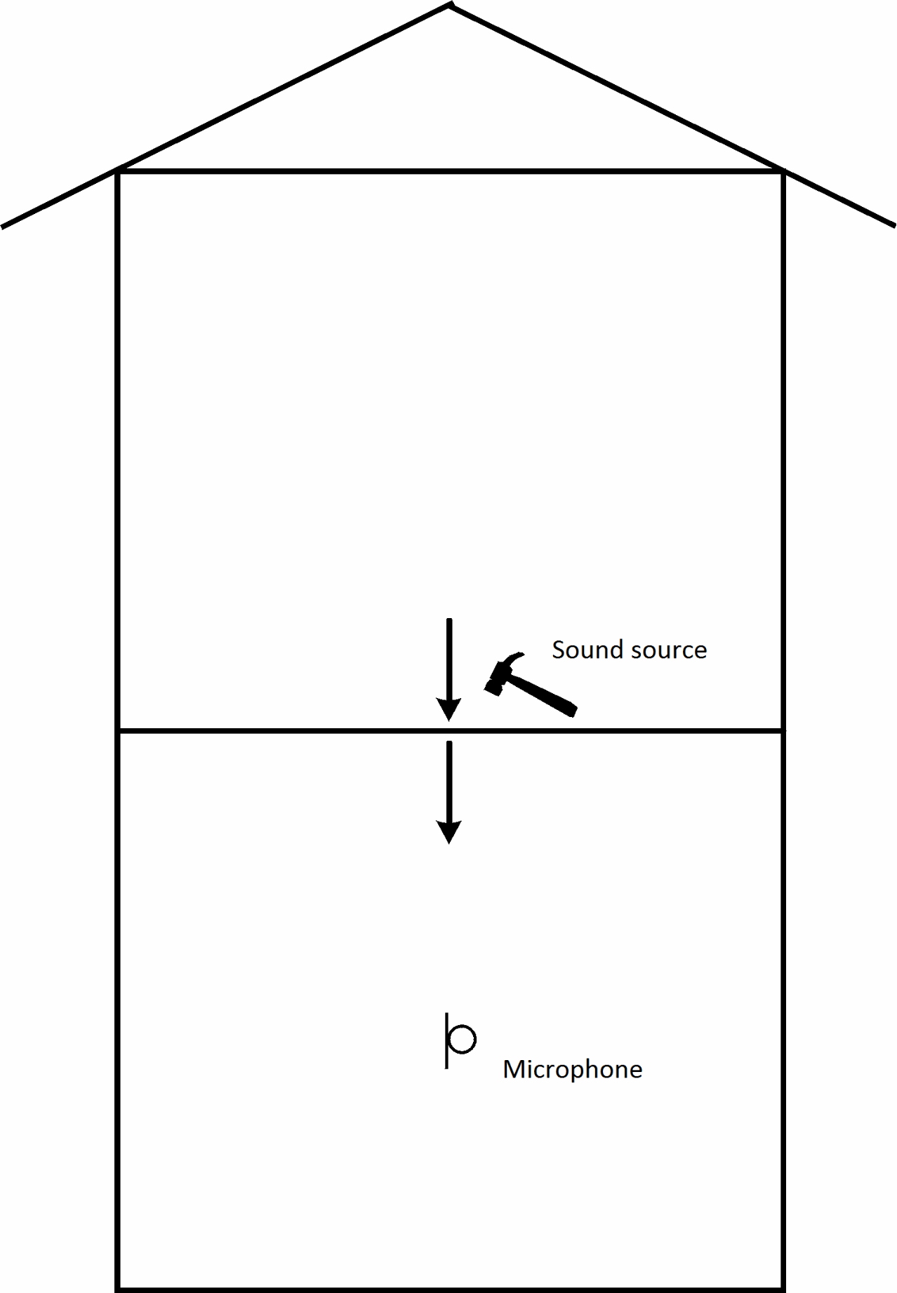
Step sound
Step sound is the result of mechanical impact, e.g. when walking on floor or deck constructions, and the sound is transmitted to and radiated in adjacent rooms, see Fig. 8.
Step-sound level, L´n,w [dB]
A single-figure measure of sound transmission to a room, when the floor of another room (usually the room above) is affected by a standard beater, see Fig. 8.
Step-sound reduction, ∆Lw [dB]
The step-sound reduction of the flooring, Δ Lw, indicates its capability to reduce and thus improve step sound. It is defined as the reduction of the step-sound level in an adjoining room separated by a dividing floor by laying flooring in relation to the step-sound level of the deck structure, see Fig. 8. The weighted step-sound reduction is indicated by a single figure.
Fig. 7
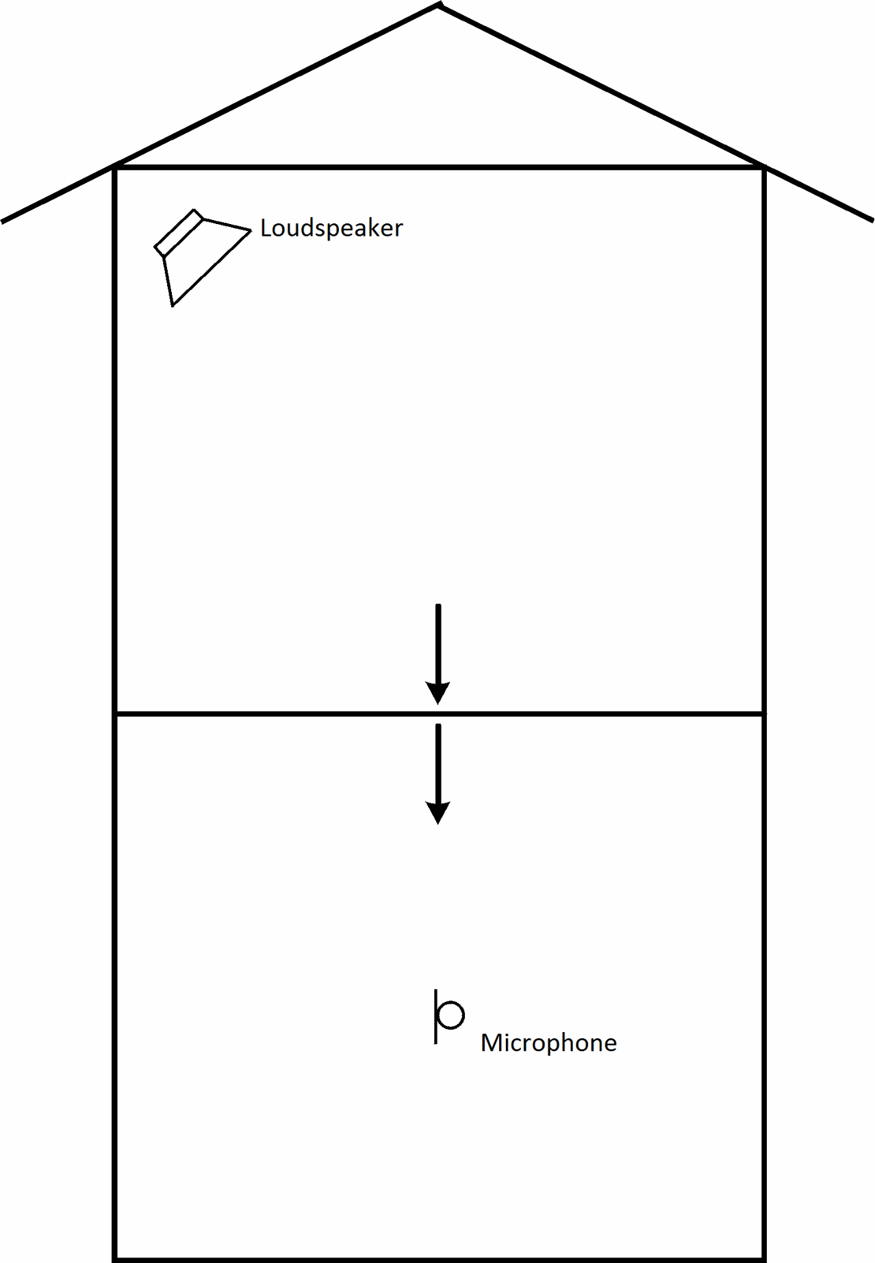
Fig. 8
Drum sound
Drum sound indicates the special type of step sound radiated in the same room from which the sound originates. Drum sound is for example common in long corridors where much noise can occur, see Fig. 9.
Reverberation time, T [sec]
Reverberation time indicates how quickly the sound pressure level falls when the noise source in a room is switched off. The reverberation time depends on the room absorption. In most rooms, a brief reverberation time is recommended, see Fig. 9.
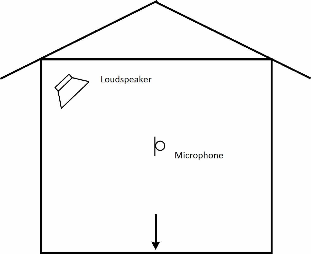
Absorption
When sound waves hit the surface of a building, some of the sound energy is absorbed.
This results in a reduction of the sound pressure/sound. The absorption can be used to reduce the noise level in rooms, see Fig. 10.
Fig. 9
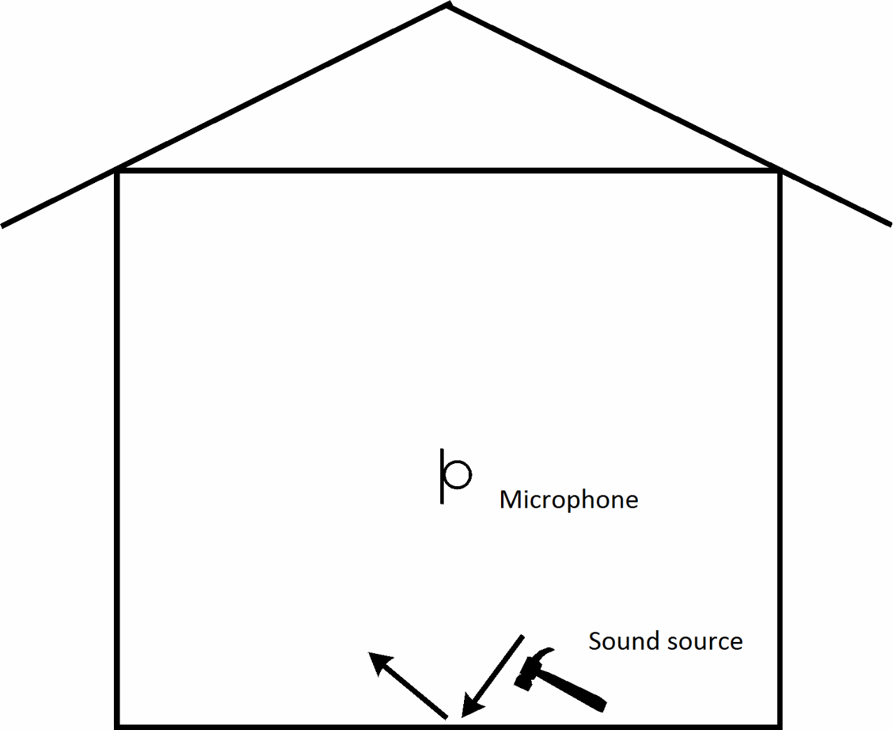
Fig. 10
LITTERATURE
SBI Instructions 166, "Building acoustics, theory and practice", Jørgen Kristensen and Jens Holger Rindel, SBI, 1989
SBI Instructions 172, "Buildings' sound insulation, new buildings", Jørgen Kristensen, SBI, 1992
SBI Instructions 173, "Buildings' sound insulation, old buildings", Jørgen Kristensen, SBI, 1992