LAYING INSTRUCTION FOR JUNCKERS LEVEL 78+ BATTEN SYSTEM
Solid Hardwood Flooring | Commercial / Residential
C 1.2.4
C 1.2.4
JUNCKERS LEVEL 78+ SYSTEM
C 1.0 General information
C 1.2 Batten Systems Information
C 1.2.3 Specifier's Information
C 1.2.4 Laying Instruction
BEFORE AND DURING LAYING THE FLOOR
The building must be weather tight. The heating system must be installed and tested and during the heating season should be in operation. Cast concrete elements, screeding and other wet trades, which contribute moisture to the building, e.g. tiling, plastering and priming of paintwork, must also be completed.
The relative humidity in the building must be between 35-65% RH and the temperature 18-22° C.
The residual moisture contained in the concrete or screed must not exceed 90% RH (UK: Concrete moisture max. 75% RH acc. to BS 8201, when checked by measurement).
Solid boards should always be laid immediately on their arrival at the building. The packing on the bundles must not be removed until just prior to laying the floor, i.e. no acclimatising of the boards on site must take place.
NB: Read these laying instructions carefully before laying begins.
In case of doubt please contact your Junckers distributor before installing the floor
Fig. 1
1. MOISTURE BARRIER
Minimum 0.20 mm polythene membrane is laid on all concrete or screeded bases.
Overlapping 200 mm at all joints. It must be placed under heating pipes and turned well up at walls, etc.
NB: If the residual moisture is above 75% RH, all overlaps must be taped using 50 mm wide tape.
Fig. 2
2. LAYING OUT BATTENS
Battens must be dry, straight and without bowing or twisting. Battens must be spaced at correct intervals. The batten centres, B and C, are determined according to the use of the floor, the expected loads and type of floor (20.5 mm Plank or 22 mm 2-strip):
Residential buildings:
20.5 mm Planks: B = 500 and C = 400 mm.
22 mm 2-strip boards: B = 600 and C 500 mm.
Distance (D) from wall to first batten max. 80 mm.
Batten end joints must be staggered (A) minimum 600 mm from the neighbouring row and must only be in a line if well connected together. Distance from batten ends to walls must be minimum 10 mm.
In commercial buildings the batten centres must be reduced according to the stipulated load class, see C 1.0 - Load classes and C 1.2.1 – Table 3.
Fig. 3
3. LAYING OUT BATTENS
If laying through doorways or similar always use at least 3 battens projecting through doorways.
Hot as well as cold water pipes must be insulated with minimum 20 mm insulation or similar
Fig. 4

4. LEVELLING OF BATTENS
Battens are levelled to a flatness tolerance of 2 mm under a 1.5 m straight edge (UK: 3 mm under a 2 m straight edge).
Centre distance between packing material according to batten dimensions and the use of the floor, see table in Fig. 4.
Centre distance (A) is used in middle batten areas and centre distance (B) at batten end joints and at batten ends. Batten end joints must be supported by two packings.
At walls, etc. the distance (C) from batten ends to the centre of the first packing must be maximum 80 mm.
Fig. 5
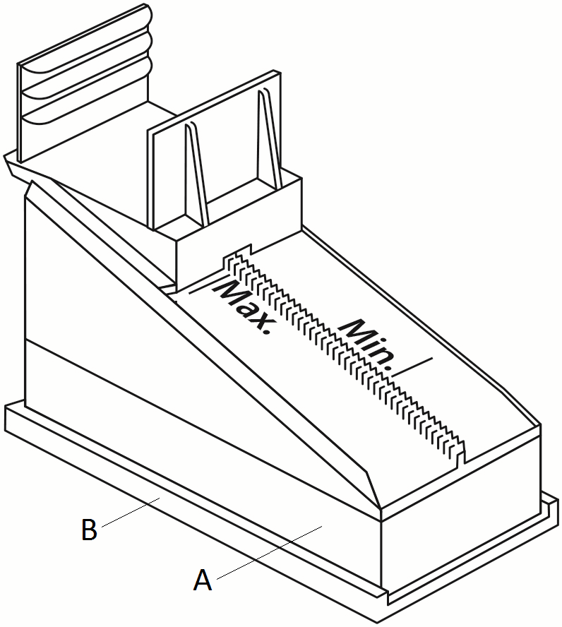
5. PACKING MATERIAL
Junckers DuoWedges are clicked onto the battens in accordance to centre distances in section 4.
Junckers DuoWedges are used alone or in combination with bases, Fig. 5 (A), and/or Junckers Stepsound Reducer, Fig. 5 (B).
Bases are available in 20, 30, 40 and 50 mm height. Only 2 bases per wedge are allowed.
All batten joints must be supported by two wedges.
NB: Do not exceed the maximum position, see Fig. 5, when levelling.
Fig. 6
6. LAYING OUT BOARDS
Lay the boards in a random joint pattern. Distribute the header joints as far apart as possible. However, the distance between board joints in two successive rows should be at least 250 mm. Stave joints in one row of boards should not be in line with stave joints in a neighbouring row, but must be spread as far as possible (min. 50 mm).
Expansion gaps to walls and fixed installations must be 1.5 mm per running metre of floor width on each side (A), and 1.0 mm per running metre of floor length at each end (B), all with a minimum size of 12 mm (UK: 15 mm).
Board end joints may occur in between battens but no more than for every third board.
Cut the last row of boards to form the correct size of expansion gaps at the wall (A).
For floors over 12 m wide it is recommended to start from the centre using a loose tongue to join the central boards together
Fig. 7
7. 10-BOARD RULE
To avoid as far as possible stress, distortion or gaps in the floor due to fluctuations in the climatic conditions in the building, the boards must be laid according to the 10-board rule which indicates the width of 10 boards when laid.
The 10-board measurement is based on the expected maximum relative humidity of the building when in use. E.g. an expected relative humidity of max. 65% RH will normally require a 10-board measurement of approx. 1293 mm.
For ship’s decking with neoprene always use a 10-board measurement of 1298-9 mm which slightly compresses the neoprene strip during installation.
In case of doubt please contact Junckers Technical Service
Fig. 8
8. 10-BOARD RULE
The 10-board measures for different board width, see table below, indicates the width of 10 boards when laid, and is based on a maximum relative humidity of 65 % RH.
This is a measurement across 10 boards, see Fig. 8, and must be checked continuously during installation.
| 10-board measurement | ||
| Board width | Normal boards | Shipsdecking |
| 129 mm | 1293 mm | 1298 mm |
| 140 mm | 1403 mm | 1408 mm |
| 185 mm | 1853 mm | 1858 mm |
Fig. 9
9. NAILING
The boards are secret nailed at a 45° angle with one nail in each board, into each batten.
Use Junckers J-Nails, 2.5 x 65 mm type-T machine nails or 2.8 x 65 mm wire nails. To ensure that the nail has the necessary shearing strength, it is important to adhere to Junckers’ above mentioned requirements for machine nails.
Do not nail any closer than 50 mm from a board- or stave end.
Alternatively, 4.2 x 45 mm screws (UK: 45 x no. 4 screws) can be used after predrilling using a 3.5-4.0 mm drill.
Fig. 10
10. VARIOUS
Around pipes, drill a hole in the board to accommodate the pipe. The space around the pipe must be the same as the expansion gap at the wall.
A tapered wedge is cut out, so that it can be glued in place. This gap is covered using a radiator pipe cover.
At door frames and architrave’s, cut the base of the frame and architrave to allow the floor to fit underneath.
At the threshold the expansion gap can be covered by a threshold strip or, if levels reduce, fit a ramp.