Laying instructions
DUOBAT 120+ SPORTS FLOOR SYSTEM
D 7.2.1
Fig. 1
Junckers Pro Complete 44
D 1.0 General information
D 1.2 Batten System Information
D 7.2 Specifier's Information
D 7.2.1 Laying Instructions
BEFORE LAYING THE FLOOR
The building must be weather tight. The heating system must be installed and tested, and during the heating season there should be a constant heat supply. Cast concrete elements, including casting of sockets for fixtures and fittings, screeding and other wet trades which can contribute moisture to the building, e.g. priming of paintwork, must also be completed.
The relative humidity in the building must be between 35 - 65% RH (UK) and the temperature approx. 16-20°C. The residual moisture contained in the concrete or screed must not exceed 90% RH. (UK: 75% acc. To BS 8201). In wooden based sub floors the moisture content should not exceed 12%.
Solid boards should always be laid immediately after arrival at the building. The packing on the bundles must not be removed until just prior to laying the floor, i.e. no acclimatising of the boards on site must take place.
NB: Read these instructions carefully before laying begins. In case of doubt please contact your Junckers distributor before installing the floor.
Fig. 2
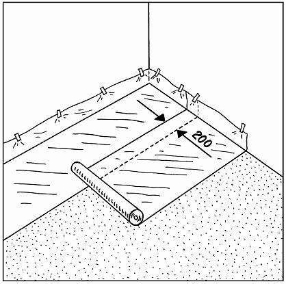
1. MOISTURE BARRIER
A moisture barrier of min. 0.20 mm PE membrane is laid.
The moisture barrier is laid with an overlap of 200 mm at all joints, continuing up walls, etc.
The polythene has to be taped at all lap joints.
Fig. 3
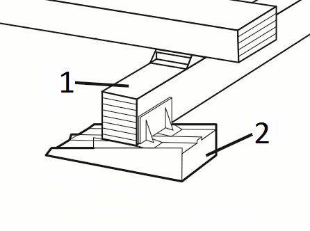
2. LAYING OF LOWER BATTENS
Before laying of the lower battens (1), the enclosed DuoWedges (2) are clipped-on onto the lower battens where marked (6 pcs. per batten).
Continue as described in part 3.
Fig. 4
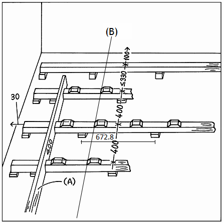
3. LAYING OF LOWER BATTENS - CONTINUING
The lower-battens are laid parallel to the longest side of the room. The first and last row of battens is laid with a distance of 100 mm from the wall to the centre of the batten (Note that these are special battens called Face Wall Battens, without J-Lock elements, and marked with yellow tape on the bundles).
The first batten, in each of the remaining rows, is special made battens called Start Battens (marked with green tape on the bundles). These are delivered in two lengths and are always used, by turns, as a starter in a new row. All the start battens are laid keeping 400 mm centre to centre, by the Spacing Batten ((A) market with black tape on the bundles), and the distance of max. 330 mm between the first and second batten row in each side of the hall are equalized. Keep 30 mm distance from wall to the end of the start battens and straighten up the J-Lock elements on a line by using a string (B). When all start battens are laid, the Lower Battens are laid in continuation of these. Fit the last batten in each row, and use the waste as extra battens at net posts, pipes, etc. See part 4.
Fig. 5
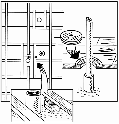
4. LAYING OF LOWER BATTENS - CONTINUING
The entire substructure (lower and upper battens) must be placed with an expansion gap of minimum 30 mm from all walls, net posts, pipes, etc. NB: The position of the lower battens must ensure that the boards are laid parallel to the longest side of the room. Place extra loose battens at net posts, pipes, etc. Loose battens must be elastic.
Fig. 6

5. LAYING OF UPPER BATTENS
Upper battens with mounted resilient pads are laid. The first and last batten rows are laid at a distance of 100 mm from the wall to the batten centre (Note that these are special battens called Gable Battens, without shock pads, and marked with red tape on the bundles). The second batten row is clipped-on to the lower battens, by the premounted JLock elements, centred at 266 mm to the first batten row. All following batten rows are centred at 336 mm.
To control the direction of – and distance between – the lower battens, every 5. row should be clipped-on to the lower battens as a start. Before installing the remaining upper battens, levelling of the substructure could be done more easily, see section 6.
Note: Each end of a batten row must be fixed straight to the face wall batten, without any intermediate shock pad or wooden block, see drawing 5.1. Batten end joints must not be in a line, but must be staggered 2 batten bay as a minimum.
Fig. 7

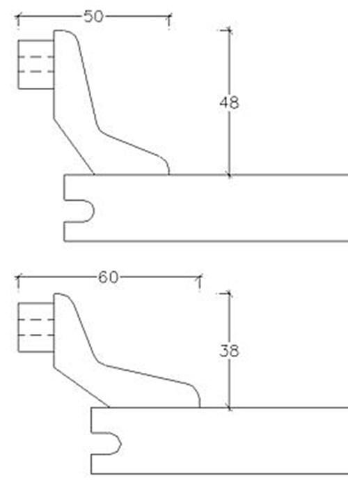
6. LEVELLING THE SUBSTRUCTURE
The lower battens (1) are levelled using the wedges (2). Extra wedges are mounted in each end of the batten rows, where the last batten is fitted by the wall.
On a subfloor levelled to a tolerance of no more than a 2 mm gap showing under a 1.5m straight edge (UK: 3 mm under a 2 m straight edge) the substructure can be laid without levelling, see D 1.1 - Flatness of subfloor.
Above mentioned wedges can be used either alone or in combination with bases(available in 20, 30, 40 and 50 mm), to achieve the right floor level/height. Use nomore than 2 bases under each wedge.
Fig. 8
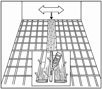
7. LAYING OF BOARDS
If the floor is more than 12 m wide laying must begin in the middle of the sports hall.
The two centre boards are joined with a loose tongue which is glued to both boards in the full length of the boards.
The boards are secret nailed, see section 10
Fig. 9
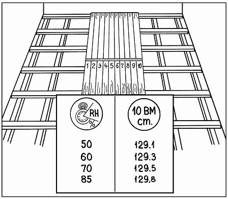
8. 10-BOARD RULE
To avoid as far as possible stress or moisture formation in the floor, due to fluctuations in the climatic conditions in the building, the boards must be laid according to the 10-board rule which indicates the width of 10 boards when laid. Compliance must be checked continuously.
The 10-board rule is chosen on the basis of the maximum expected relative humidity of the building over the year, see also D 1.2.
The measurement is achieved by inserting temporary spacers between the boards during the installation process.
In case of doubt please contact Junckers Technical Services.
Fig. 10

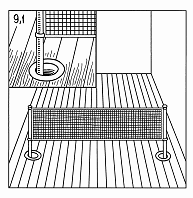
9. BOARD PATTERN
All board header joints must be fully supported and all boards must be laid in the pattern shown in the drawing.
NB: The distance between board header joints in two consecutive rows must be 4 x 336.4 mm = 1345.6 mm, as shown in the drawing.
Fig. 11

10. NAILING
Use Junckers machine J-Nails, 2.2 x 45 mm.
The boards are secret nailed at an angle of 45°. Do not nail closer than 50 mm to stave joints and never in the board end joints.
To avoid creaking, the boards are pressed down on the battens while they are nailed.
The distance between the floorboards and walls/vertical fixed installations is calculated as 1.5 mm per running metre of floor width on each side, and at end walls 1 mm per running metre of floor length, with an overall distance of minimum 30 mm.
NB: The first and last rows of boards installed must be face nailed or screwed and then covered with matching filler.
11. BUSHINGS
On mounting of bushings in the surface of the floor the internal diameter of the bushing must exceed that of the pipe, i.e. the external diameter of the net pole, by at least 40mm. At the outermost zones of the floor all bushings are mounted eccentrically towards the middle of the floor in relation to the sockets in the concrete.
NB: Floor rosettes must be mounted to allow both vertical and horizontal movement of the floor to take place unimpeded.
12. SKIRTING
Junckers Combi Sports Skirting is installed.
The skirting can also be mounted by another method, provided that it ensures the free movement of the floor and includes ventilation space.